Send Email to
Us
Send Email to
UsFor inquiries about our products or price list , please leave your email to us and we will be in touch within 24 hour


AS/NZS 3675 Aluminum XLPE Covered Conductor Type CC Type CCT
DOWNLOAD CATEGORY SPECIFICATIONS
Application
AS/NZS 3675 standard covered conductor is covered with insulation material but without conductor or insulation screens. They must be used in a similar manner to open wire 11 to 33kV bare overhead systems.
Classification
There are two main types of covered conductors as follow: CC and CCT. Chialawn can provide perfect recommendations on the most suitable installation conditions and fittings for both systems.
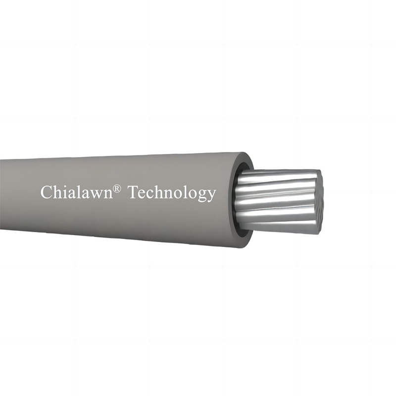
Covered Conductor CC
CC covered conductors have a covering with a minimum average thickness of 2.0mm for use on all working voltages up to and including 19/33kV. CC can withstand intermittent contact with conductive material between phases or to ground, e.g. trees and branches, but should not remain in permanent contact.
1. Conductors:
conductors are available in aluminium, aluminium alloy and aluminium clad steel.
2. Water blocking:
water blocked with a special material meeting all the test requirements of AS/NZS 3675.
3. Covering:
conductors are covered with a track resistant UV stabilised XLPE.
4. Marking:
CC are marked on the external surface with “CC”, logo, year of manufacture, and conductor material. They are also marked with sequential six-digit numbers at 1-metre intervals, with the lowest number at the inner end of the drum.
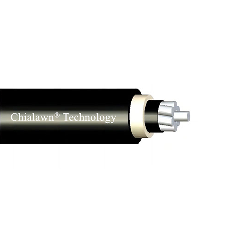
Covered Conductor CCT (Full Thickness Covering)
CCT covered conductors have a specified thickness of covering for each of the nominated working voltages. While still required to operate under similar principles to a bare wire or CC system, they have electrical and mechanical characteristics which permit them to remain in contact with tree limbs for an extended period dependent on abrasive characteristics of the tree, frequency and strength of prevailing winds and operating temperature.
CCT show better performance in polluted environments. They are suitable for use in spacer cable systems and in the Insulated Unscreened Conductor (IUC) systems.
1. Conductors:
conductors are available in aluminium, aluminium alloy and aluminium clad steel.
2. Water blocking:
water blocked with a special material meeting the test requirements of AS/NZS 3675.
3. Covering:
conductors are covered with a track resistant UV stabilised XLPE or with an inner layer of non-UV stabilised XLPE,and an outer layer of UV stabilised High Density Polyethylene (HDPE). In the latter case, the average thickness of HDPE is not more than 40% of the specified minimum average thickness, and not less than 1.0mm.
4. Marking:
CCT are marked on the external surface with “CCT”, logo, year of manufacture, and conductor material. They are also marked with sequential six-digit numbers at 1-metre intervals, with the lowest number at the inner end of the drum.
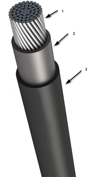
1. Aluminium Conductor
2. Water Blocking
3. Covering
Specifications
AS/NZS 3675 Standard Covered Conductor